
Fuel-tank sloshing is the oscillation of the free fuel surface in a partially filled tank caused by rapid acceleration, braking, cornering, and curb strikes. On a race track these transient loads are large and abrupt, so the moving fuel can generate waves, impact internal walls, and momentarily uncover the pickup. This “sloshing” shifts mass, creates pressure loads on the tank walls, and risks uncovering the pickup. In racing, even a momentary loss of fuel supply can cause hesitation, reduced performance, or mechanical damage. To manage this, tanks are equipped with baffles, surge pots, or anti-slosh foam that dampen wave motion and ensure reliable pickup coverage. Simulation helps engineers predict how fuel behaves under track conditions, evaluate suppression measures, and optimize designs for both performance and durability. The simulation approach used here builds on our previous validated tank sloshing case, demonstrating the reliability of shonDy for predicting free-surface dynamics.
案例说明
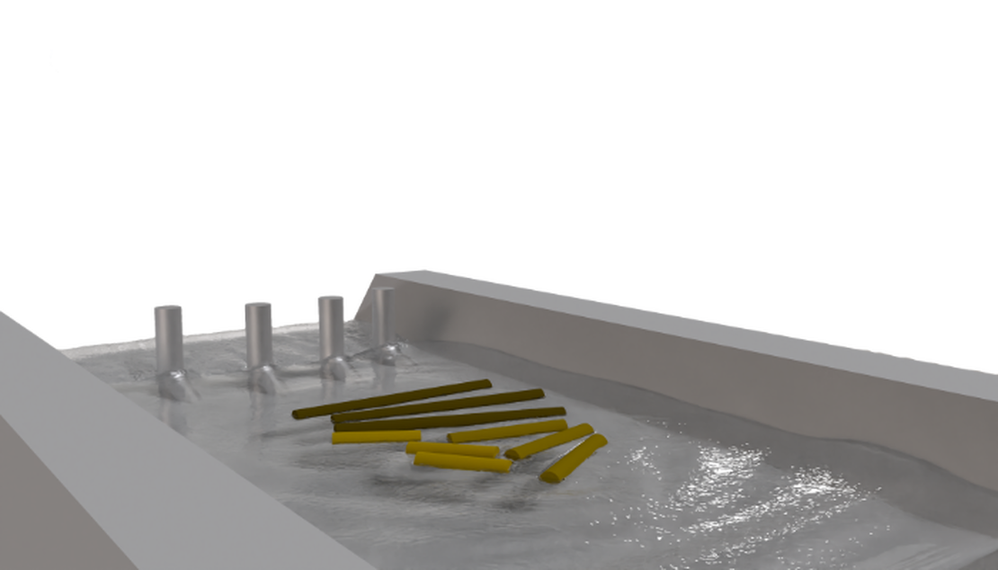
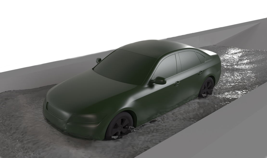
The driving conditions for this study were based on acceleration data recorded during a private track session at the Lausitzring, kindly provided to us for simulation purposes. The dataset was collected with the Porsche Track Precision App and represents a complete lap.
For the analysis, a generic fuel tank model from an open-source library was used instead of the original vehicle tank. This approach allowed us to focus on the sloshing behavior itself without relying on proprietary geometry. In a subsequent step, the same tank was modified with two different baffle configurations:
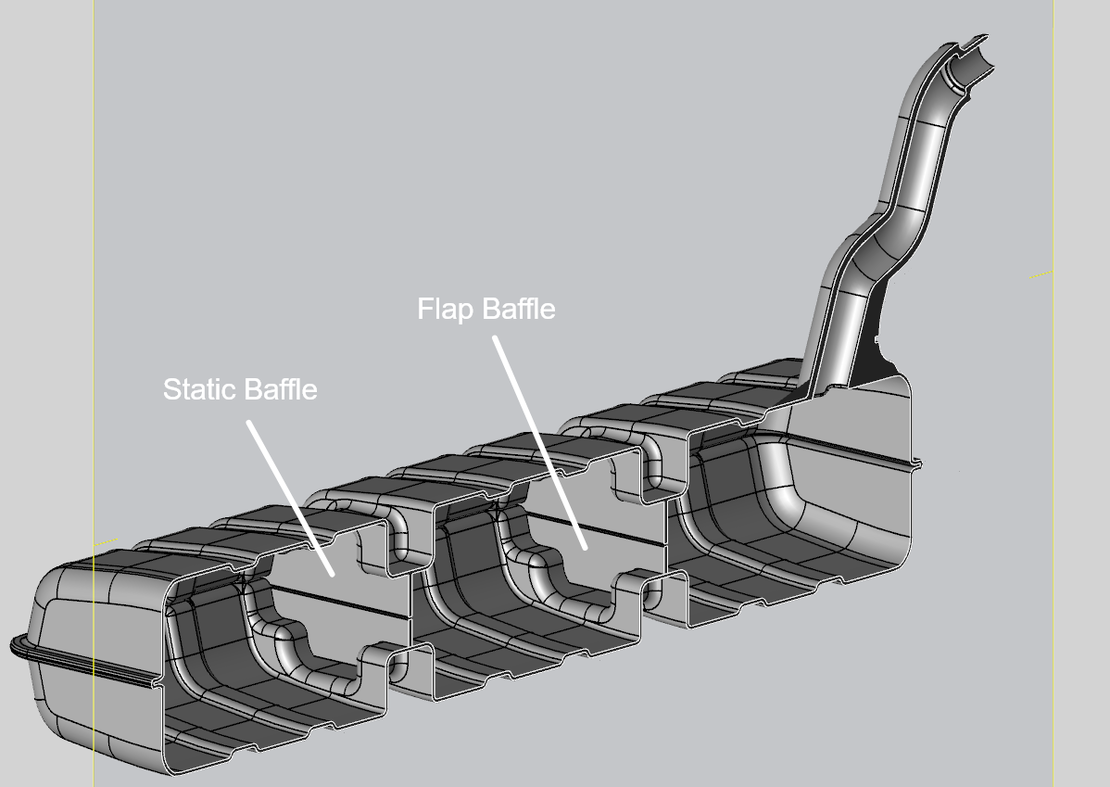
- Static baffle setup – Baffles were added in both longitudinal and lateral directions, enabling a direct comparison of fuel motion with and without conventional suppression features.
- Flap baffle setup – A design where movable flaps act as dynamic barriers, further influencing the flow. The detailed geometry and operating principle of this setup are described in the subsection below.
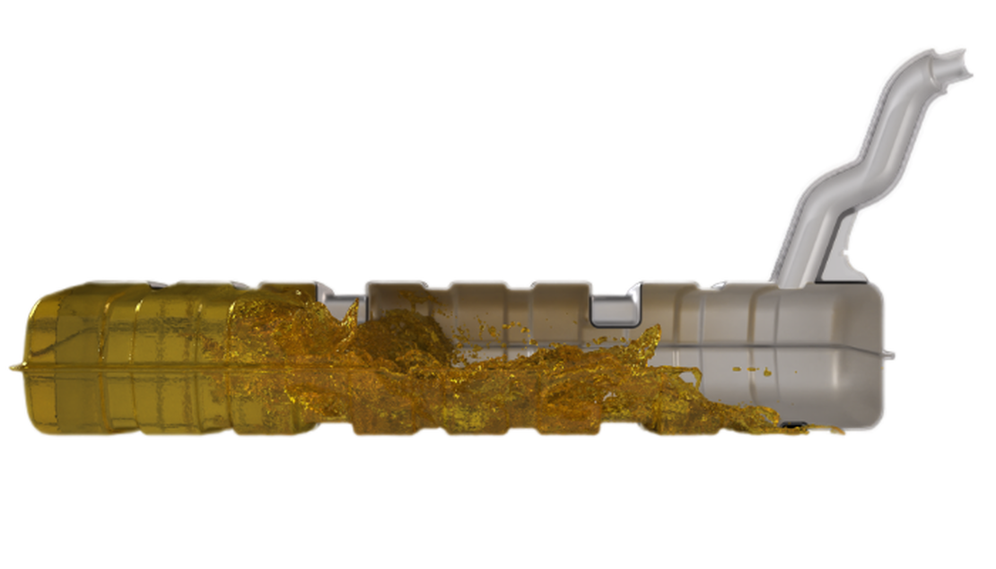
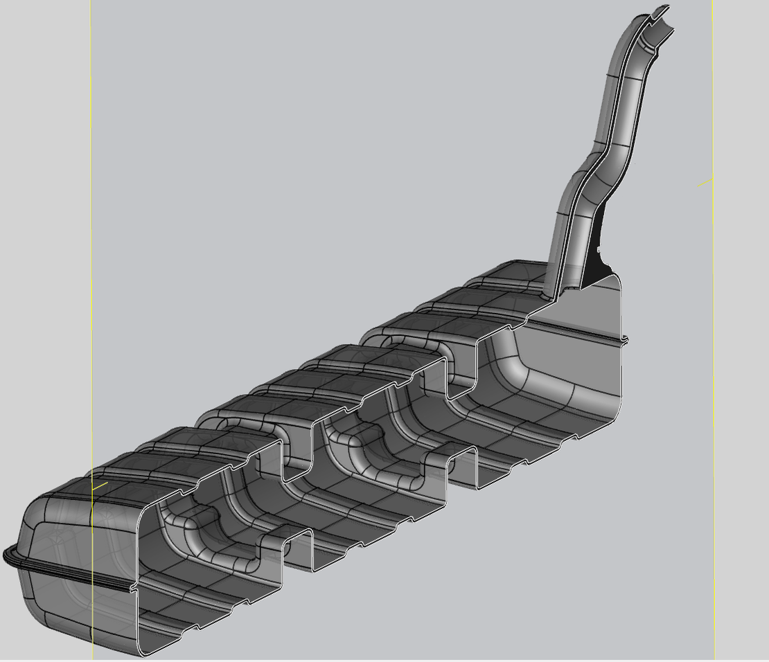
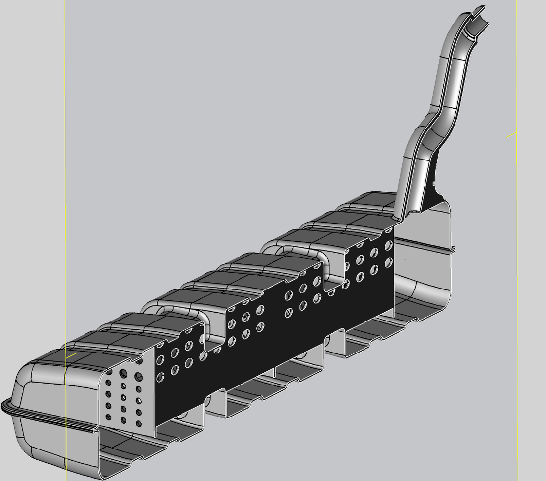
The geometry of the no-baffle and static-baffle tanks is shown in the images below.
Flap Baffle Setup
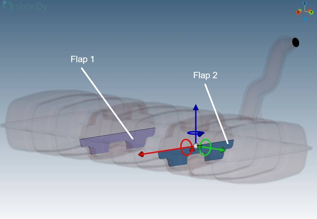
In addition to the static baffles, a second configuration with flap baffles was investigated. Two baffles were placed in the lateral direction, but unlike the static design, their lower sections were connected to joints that allowed controlled rotation. The upper sections remained fixed, functioning as conventional static baffles.
The flaps were not completely free in their movement but constrained depending on the driving direction:
- Clockwise direction (as seen in the images): No rotation was allowed. After a short backswing, the flaps acted effectively as static baffles, providing resistance during right-hand turns.
- Counter-clockwise direction:
- Flap 1 was allowed to rotate between 0° and 90°,
- Flap 2 was allowed to rotate between 0° and 45°.
This asymmetric behavior enabled the flaps to open selectively depending on flow direction, offering reduced resistance in some cases while still functioning as barriers in others. The geometry and configuration are illustrated in the images below.
仿真结果
The first video shows an overview of the simulation with the tank in the no-baffles configuration. The footage begins as the driver approaches Turn 1 (T1). The video is split into two segments: the first covers T1 to T5, and the second spans T12 to the finish line.
In the upper half of the video, the simulated tank and hence, the movement of the fuel can be observed. Even under relatively moderate driving conditions—where the driver is not pushing the car to its limit—the fuel exhibits strong lateral motion in response to track forces.
This demonstrates that sloshing is already noticeable under typical race-track conditions. In high-performance scenarios, where every tenth of a second matters, even these small mass shifts can negatively affect vehicle balance and handling.
Baffle Performance
The second and third videos focus on Turns 1 to 5, comparing the fuel motion in three configurations: without baffles, with static baffles, and with flap baffles.
Static Baffles
In the static setup, a clear difference in fluid behavior is visible:
- With baffles: The fuel is more evenly distributed and its movement is damped. The center of mass (CoM) ultimately reaches the same position as in the no-baffle case, but the transition is slower due to the baffle restrictions.
- Without baffles: The fuel remains compact, shifting rapidly from one side to the other.
This is directly confirmed by the lateral CoM visualization in the video:
- Green cross: CoM without baffles.
- Yellow cross: CoM with static baffles.
At the start of the turn, the green cross moves significantly faster than the yellow one, highlighting how static baffles reduce rapid mass shifts and improve stability.
Flap Baffles
The flap baffle setup shows distinct behavior compared to both the static and no-baffle cases:
- With flap baffles: The fluid is retained longer in the right compartment, shifting more gradually toward the center and left side.
- Comparison:
- In right-hand turns, the fluid’s movement is damped much more strongly than in either of the other setups.
- In left-hand turns, the flaps allow greater freedom of movement, so the fluid shifts almost as fast—or in some cases slightly faster—than in the static setup, but still slower than without baffles.
The CoM visualization confirms these observations:
- Green cross: CoM without baffles.
- Yellow cross: CoM with static baffles.
- Pink cross: CoM with flap baffles.
This highlights how the flap design creates an intermediate effect—providing strong damping in one direction while allowing freer flow in the other.
Center of Mass Velocity
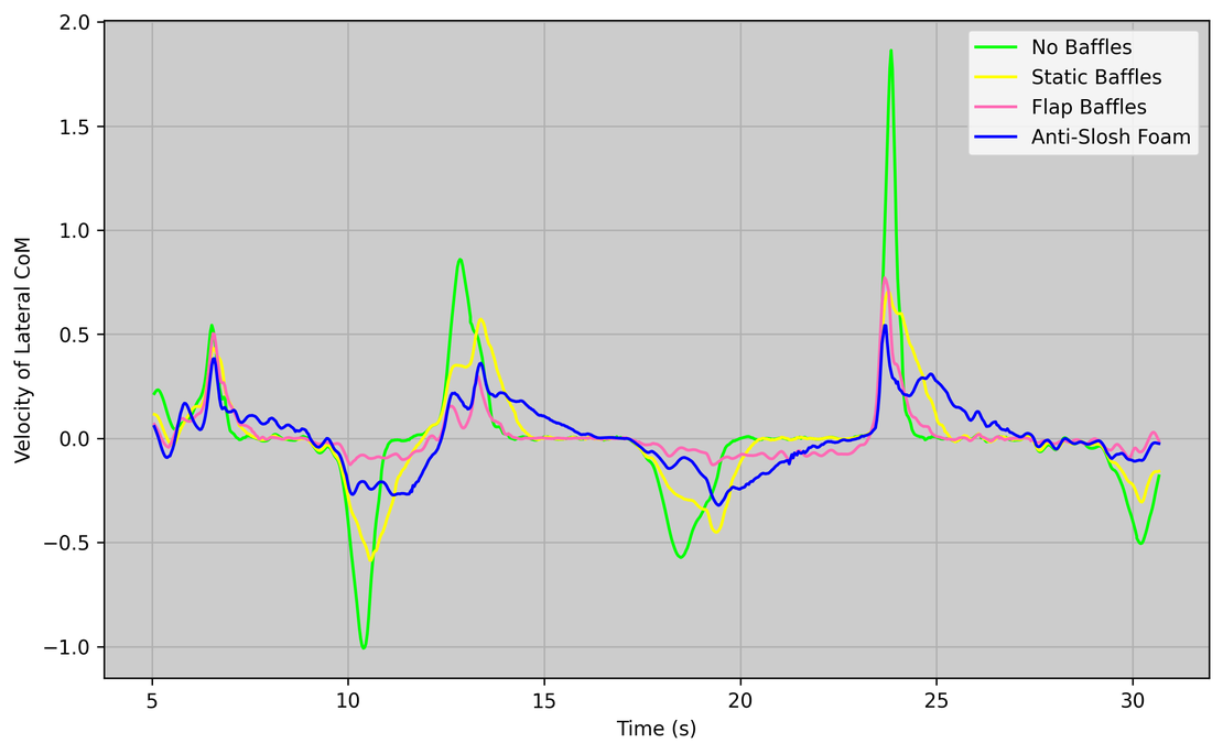
The diagram below illustrates the velocity of the center of mass (CoM) over time.
- No baffles: The CoM moves significantly faster, at times reaching double or even triple the velocity compared to the baffled cases. Sharp spikes in velocity highlight rapid acceleration and deceleration of the fluid.
- With baffles: Both static and flap baffles generate broader, smoother velocity profiles, showing the damping effect of the structures.
- Flap baffles: In right-hand turns (negative values), the velocity is strongly damped, with only minor fluid motion. In left-hand turns, the velocity is comparable to the static baffle case.
Toward the later parts of the lap, the differences between setups become more pronounced—an outcome of all three simulations starting from the same initial fluid distribution.
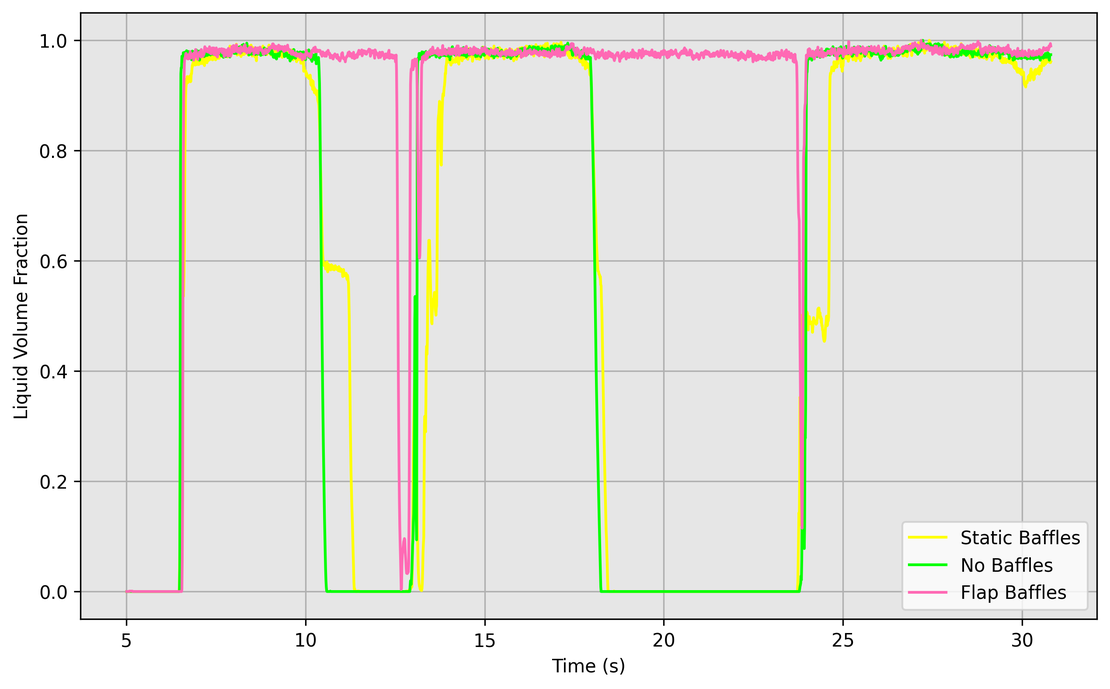
Pickup Coverage
The second diagram evaluates fuel coverage at the pickup. Reliable coverage is crucial for ensuring a stable fuel supply. To assess this, a small sample window was placed directly in front of the pickup, allowing continuous monitoring of whether fluid was present at that location (see image below).
The results show:
- Static baffles: Only a slight improvement compared to the no-baffle case. In practice, pickup coverage remains nearly the same.
- Flap baffles: A significant improvement. Since the pickup is located in the right compartment, the flap configuration restricts outflow to other compartments while still allowing fluid to return freely. As a result, the pickup remains covered almost continuously, with only two short interruptions during the lap.

总结
In this case study, a full-lap simulation of a partially filled fuel tank on the Lausitzring “Grand Prix Layout” was performed to investigate tank sloshing under real driving conditions. Acceleration data recorded during a private track session was used to replicate braking, cornering, and acceleration maneuvers.
A generic tank model from an open-source library was simulated in three configurations: without baffles, with static baffles in both longitudinal and lateral directions, and with flap baffles in the lateral direction. The simulations visualized fuel movement, lateral mass shifts, and center of mass behavior throughout the lap. Additionally, fuel coverage at the pickup was monitored via a small sample window to quantify fluid availability over time.
The results show that static baffles reduce rapid lateral shifts and dampen fluid motion, while flap baffles provide an intermediate effect: strongly damping movement in one direction while allowing freer flow in the other. The flap baffles also improved pickup coverage, keeping the intake nearly continuously supplied, whereas the static baffles produced only minor improvement over the no-baffle setup.
Overall, these simulations demonstrate that transient free-surface CFD can capture dynamic fuel behavior under realistic race-track conditions. The approach provides a robust foundation for evaluating and optimizing tank geometries, baffle designs, and fuel intake placement, enabling engineers to test and refine modifications virtually before physical prototyping.