
电驱动单元(EDU)是将电机和变速箱结合在一起的复杂系统,通常在苛刻的热条件下运行。 除了有效的润滑,管理热行为对于保持部件的完整性、避免过热以及在整个工作范围内确保最佳性能至关重要。
EDU设计中的一个关键挑战是全面理解热行为与润滑行为的耦合。 虽然适当的油液分布确保了润滑并有助于损耗的热量排出,但分析部件温度并识别潜在的过热点需要先进的仿真技术。 这对于像绕组这样的温度敏感部件尤其重要,超过热限值可能导致绝缘损坏和系统故障。
本仿真案例展示了基于粒子法的润滑分析与一维热网络建模的结合,提供了在实际运行条件下EDU性能的完整热特性描述。
目标:热 - 润滑耦合分析
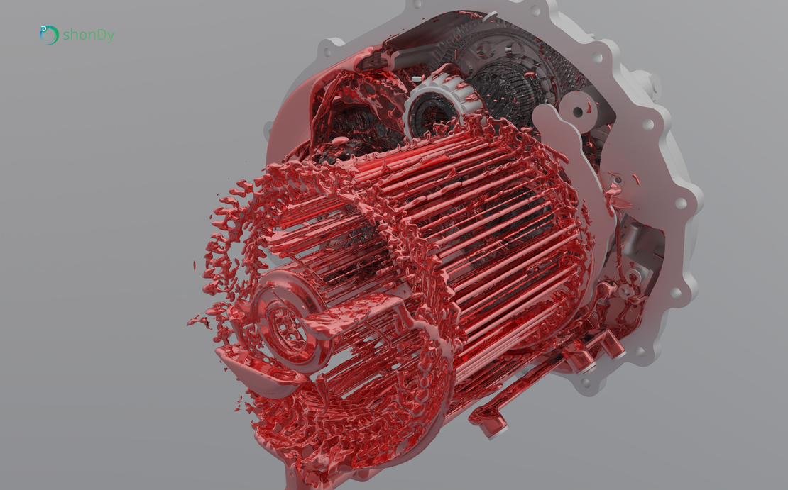
主要目标是通过耦合仿真模型,对EDU的热行为和润滑行为进行模拟。 This approach combines shonDy, which provides heat transfer coefficients and oil distribution through particle-based lubrication analysis, with shonTA, which predicts component temperatures using 1D and 3D thermal analysis. 我们在官网前期推文中已经详细探讨了EDU中的油液分布。 如果您主要关注润滑问题,请参考我们的深入案例研究。(/case-studies/edu_part2/)
通过耦合这两个工具,仿真能够全面洞察热性能,识别关键温度区域,并验证整个EDU系统的冷却效果。
案例说明
EDU运行条件
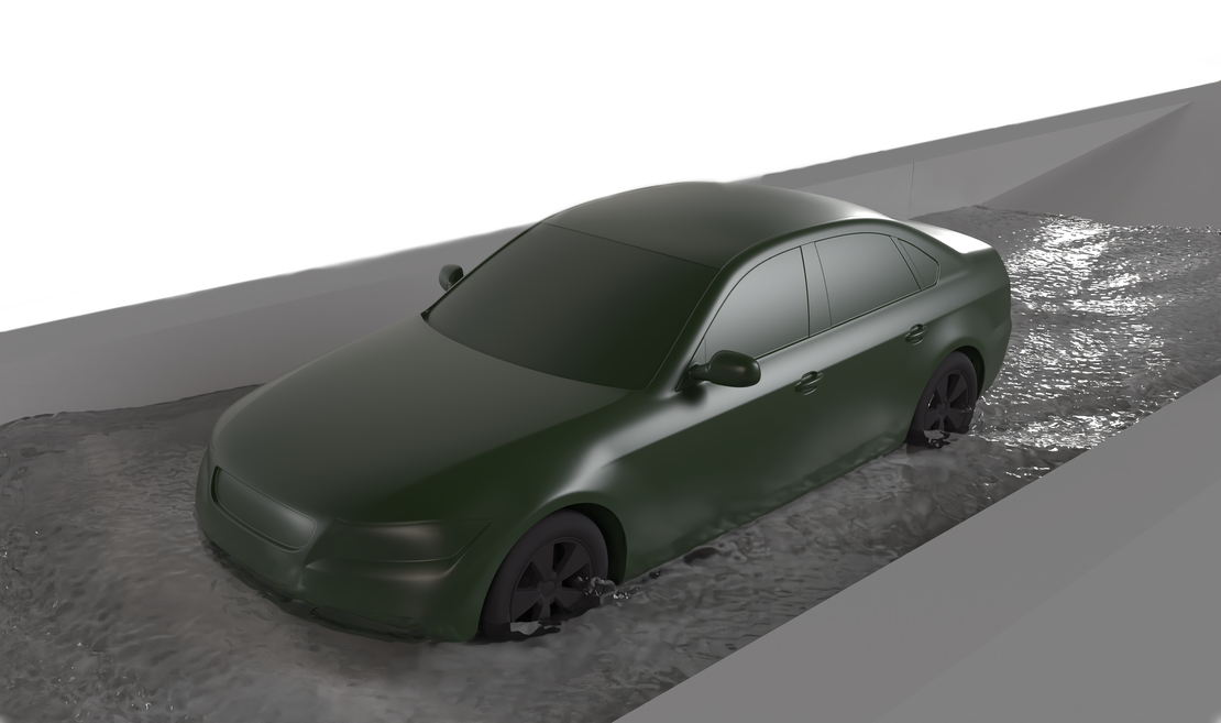
本案例分析的EDU在以下边界条件下进行:电机转速为2000 RPM,输出变速箱转速约为150 RPM,总油量为1.6升,轴流量为12 L/min,热损失约为9kW。
仿真设置
该集成方法结合了两个互补的工具。 shonDy is used with almost the same case setup as described in our in-depth case study. 主要区别在于对指定表面(如轴、转子、绕组和定子)启用了传热建模。 这使得可以计算换热系数(HTC),然后将其导出并作为shonTA的输入数据。
shonTA基于这些数据并结合了三种不同的网络类: 热接触传导(TCC)模拟直接接触固体之间的热传导;一维流网络替代了耗时的大型CFD仿真(适用于轴内油道等简单几何形状);一维热网络则通过对流、传导、对流和辐射将所有部件连接起来。 在本案例中,流网络简化了轴通道,而对流模块直接使用来自shonDy的HTC数据,以体现真实的管道流冷却行为。
热接触传导(TCC)
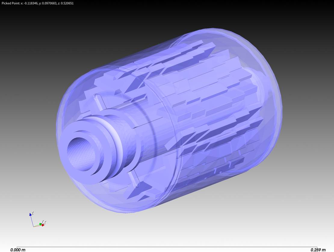
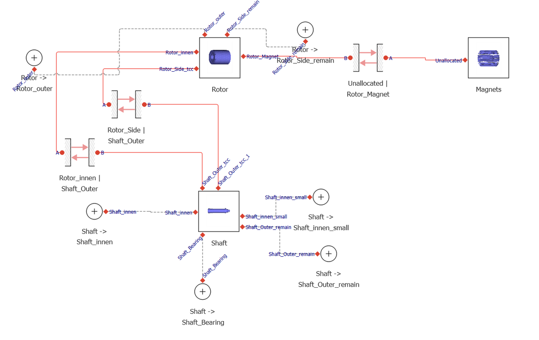
TCC模块通过三维有限元仿真预测固体之间的接触热传导。 这样可以准确预测部件界面处的热流。 例如,轴、转子和磁钢就是通过这种方式进行热连接的。 下图展示了这些连接的三维几何形状和网络表示。
一维流网络
一维流网络模块模拟流体在管道、弯头、阀门和接头中的流动,有效地替代了耗时的三维CFD仿真(适用于简单几何形状),同时保持了准确性。 该网络与热网络耦合,以实现整个流体系统的温度预测。
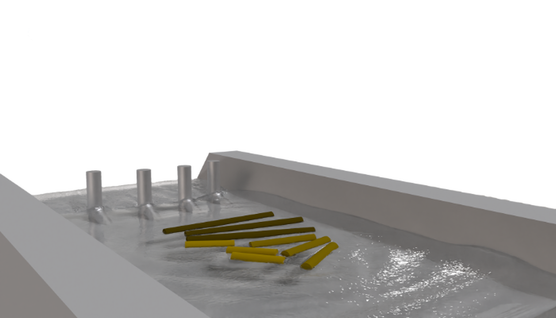
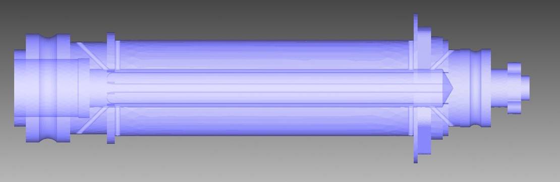
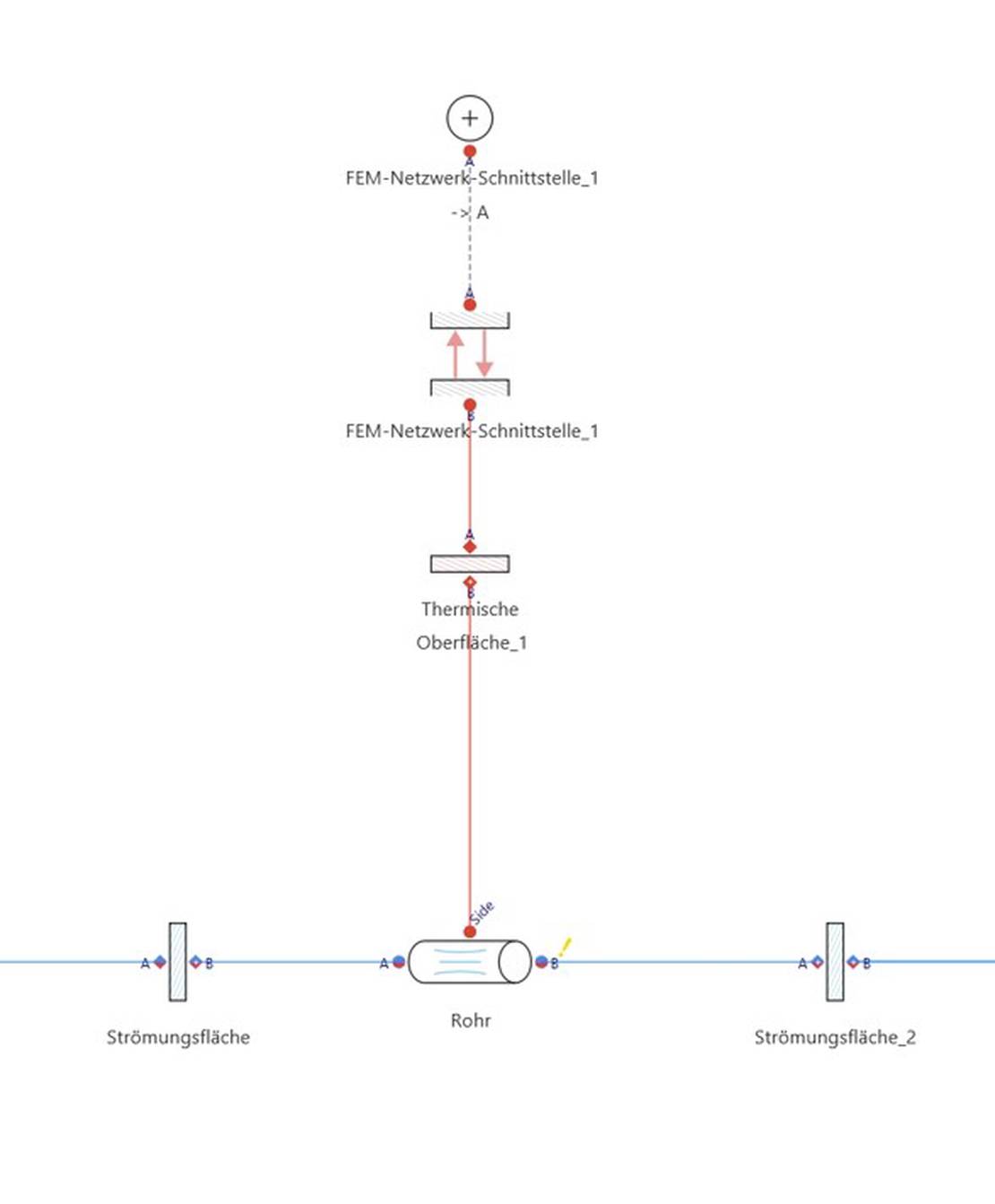
下面的示例展示了轴内的油道,包括一个大的主通道和八个较小的子通道。 整个子系统通过一维流网络方法进行简化,并保持与轴的热连接。 仿真没有使用计算量大的三维CFD,而是采用了简化的管道流动模型,这些模型彼此连接并与三维有限元模型连接。 右图展示了一个子通道的部分一维网络表示,说明了如何使用这种方法有效地模拟复杂几何形状。
一维热网络
一维热网络模块模拟包括对流、热传导、接触传热和辐射在内的综合热效应,热连接系统中的所有部件。 该方法能够进行快速的系统级温度分析,同时保持关键设计决策所需的准确性。
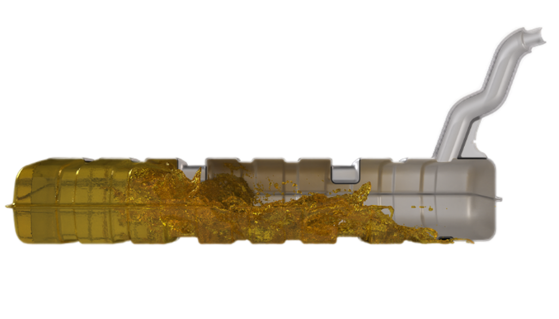
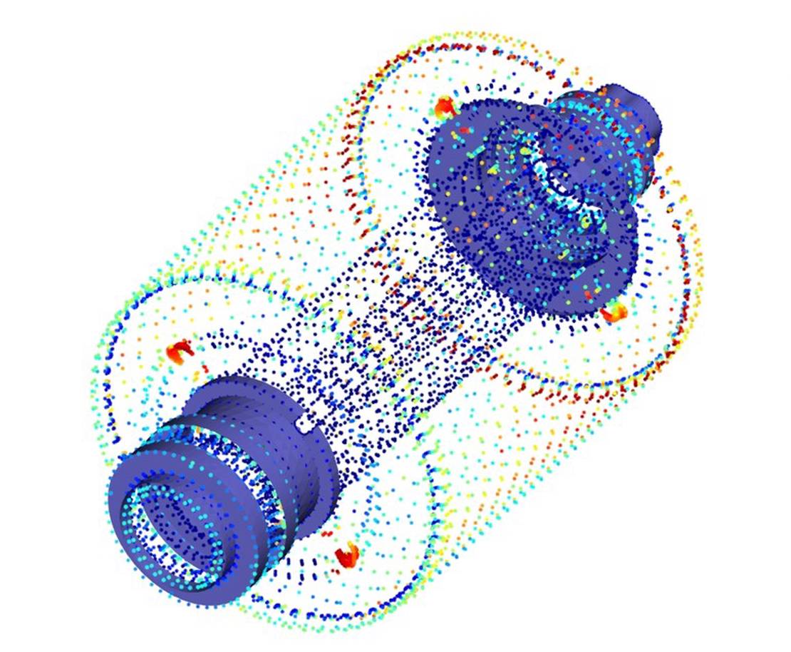
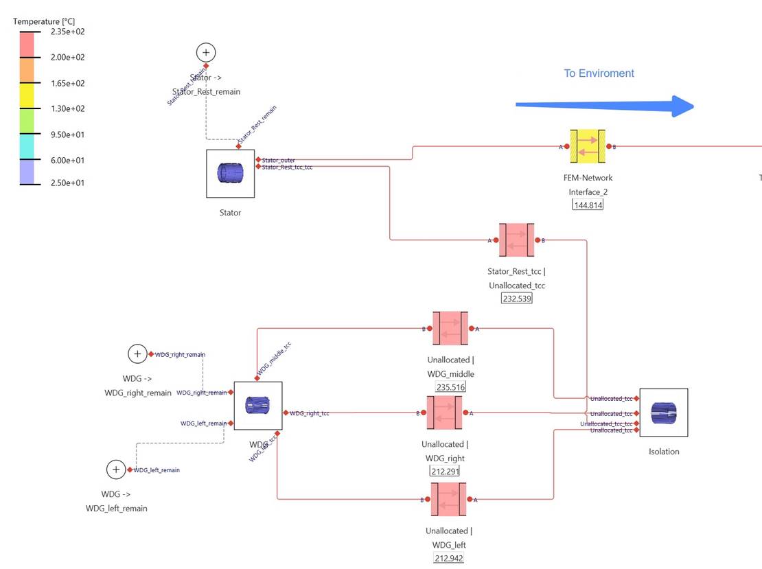
集成过程从shonDy仿真提供的换热系数(HTC)结果开始,如下图所示。 这些结果以点云数据集的形式提供,作为shonTA对流传热模块的输入数据,确保热分析基于真实的流动计算的传热边界条件。
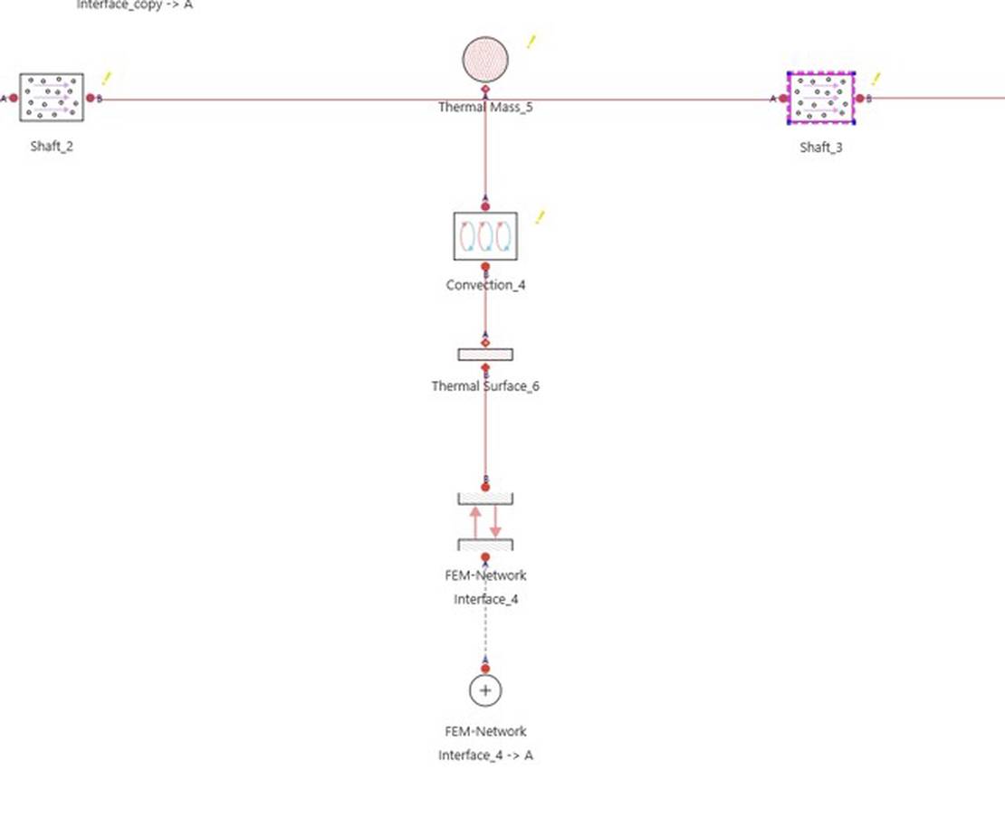
后图像展示了对流传热模型的集成,利用HTC数据、流动属性、油温和其他热边界条件来计算不同固体部件的温度行为和变化。 这种耦合方法确保了流体动力学和热效应在最终温度预测中得到准确体现。
仿真结果
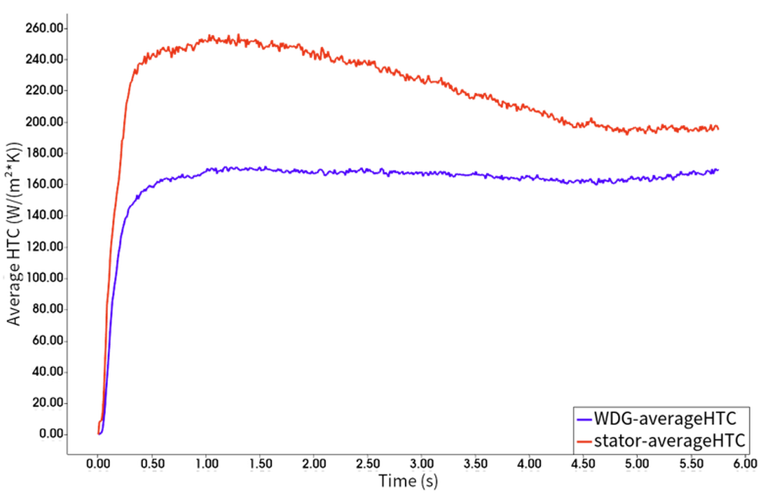
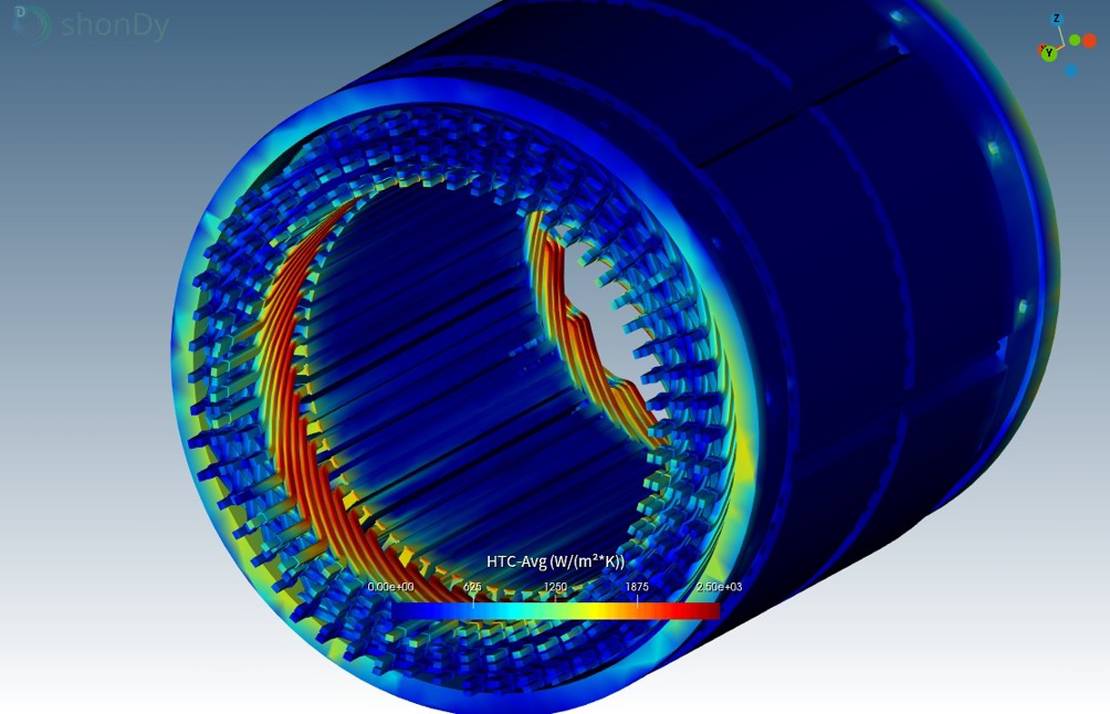
shonDy – 换热系数分布
shonDy仿真提供了关键的界面数据,HTC在约4.5秒后达到稳定。 绕组的平均HTC为160 W/m²K,定子的平均HTC为200 W/m²K。 下图显示了5秒后的油液分布,以及绕组和定子表面的HTC三维分布。
shonTA – 热分析
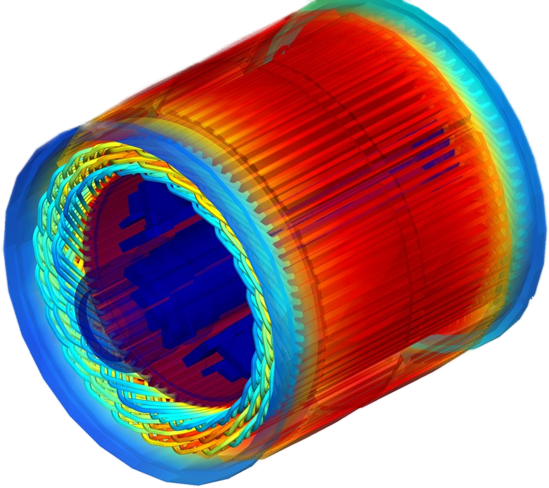
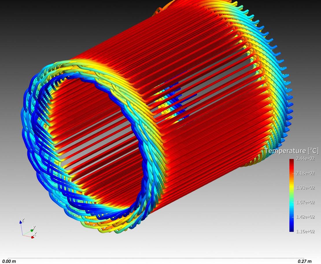
热分析显示工作温度范围从80°C(初始油温)到235°C。 传热遵循明确的路径:能量从绕组流向定子,并最终释放到环境中。
仔细观察绕组可以发现明显的温度变化。 绕组的端部由于直接接触油液,保持显著较低的温度,而中间部分则成为最热的区域。 该区域与定子电绝缘,这也起到了热屏障的作用。 因此,热量无法直接导出,主要通过绕组端部进行导热,并在那里更有效地散热。
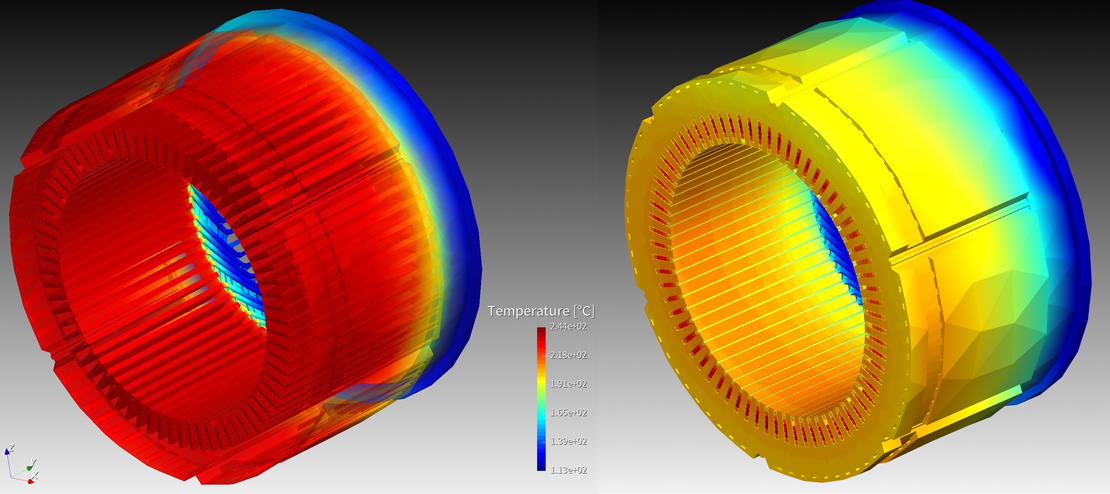
运行十分钟后,稳态仿真(左)和瞬态仿真(右)的比较突显了这种热阻。 在瞬态情况下,绕组和定子之间形成了明显的温度梯度,而在稳态情况下,这些梯度随着时间的推移变得更加平滑。
关键发现与设计建议
分析揭示了一个严重的过热问题:绕组温度高达240°C,超过了允许的工作限值180°C,超温60°C。 这个问题对部件的完整性和整个系统的可靠性构成了严重风险。
为了解决这个问题并改善EDU性能,建议采取以下措施: 通过优化轴的喷射模式,提升冷却效果,更好地针对热点降温;同时,建议在定子上增加额外的油冷喷淋流道,以提供替代的散热路径。 最后,建议将仿真扩展到具有不同负载和EDU倾斜角度的多个工作点,以确保整个工作范围内的稳健热性能。
总结
本案例研究展示了使用shonDy和shonTA进行耦合仿真的强大能力。 shonDy提供了详细的冷却滑油分布映射和HTC计算,为仿真提供了真实的边界条件;而shonTA则提供了系统级的热评估、温度预测和关键热路径的识别。 两者结合,可以在实际条件下对EDU部件进行完整的热特性描述,从而能够早期识别过热风险并指导有效的设计优化。